From Hobby Chickens to the IoT World — Part 4
From Hobby Chickens to the IoT World — Part 4
Most ventilation units, such as the ILTO 440, lack monitoring sensors for temperature, humidity, or pressure. Even if some models do include such sensors, they cannot be integrated into IoT systems using the MQTT protocol. My idea is to create a sensor case without any screws, allowing the sensor to be installed inside the ventilation unit using a strong neodymium magnet. We will need three identical sensor cases and sensors: one for incoming air, one for outgoing air, and one for the air blown into the rooms. Temperature differences indicate the performance of the heat recovery core in the ventilation unit and can reveal anomalies, such as temperature fluctuations caused by heating the sauna. Humidity differences show how the heat recovery core removes moisture from the outdoor air and whether the ventilation system operates efficiently after activities like sauna use or showering. Pressure differences provide insights into the performance of filters, for example.
Data from the ventilation unit can easily be transferred via MQTT to an InfluxDB database, where it can be visualized and further automated using Grafana. In the following image, you can see data collected from inside the ventilation unit over past 30 days:
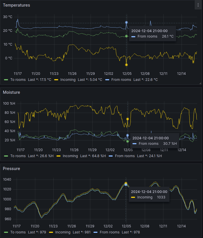
30 day information from the HVAC system
The following graph shows two days of data, illustrating how the frost protection of the ILTO 440 ventilation unit works. When the incoming air temperature drops below freezing, the intake fan stops to prevent the heat recovery core from freezing. Both temperature and humidity fluctuate as a result.
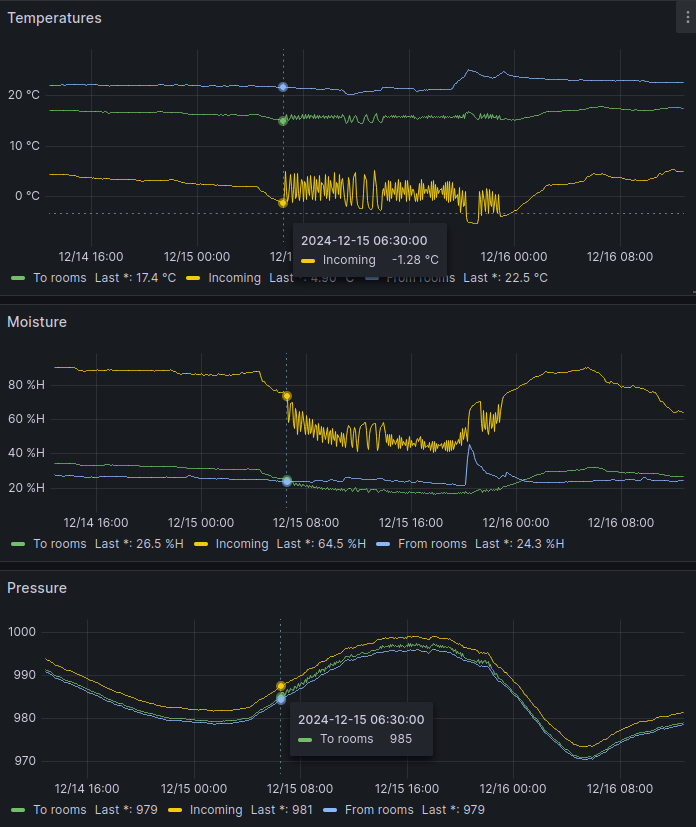
ILTO 440 fluctuation due to freezing temperatures
In this simple example, I will demonstrate in detail how I create 3D objects in Autodesk Fusion 360 for a printable case for the BME280 sensor. I use sensors designed for the I2C bus that operate on 3.3 volts. For instance, the ESP32 microcontroller has two I2C buses, allowing up to 2 x 2, or four, BME280 sensors to be connected directly to a single ESP32. Why four? Because the BME280 uses two different addresses. Other devices can also be added to the same I2C bus if the address is not the same as with BME280s. The price of a BME280 sensor on AliExpress is approximately 2 euros per unit.
🔧 Pro Tip – Use Parameters for Easy Adjustments
Before sketching, open the Change Parameters dialog (Modify > Change Parameters) and define user parameters. For example:
WallThickness = 2 mmClearance = 0.2 mmMagnetDiameter = 20 mmPCBLip = PCB_Thickness + 0.2 mm
Then in sketches and extrusions, type e.g. WallThickness instead of 2. Later you can tweak all dimensions from one place – perfect for iterative 3D printing.
When designing printable cases, the plan must take into account the operational requirements of the 3D printer. I typically use a 0.2 mm layer height and 1.75 mm filament (PLA, PETG) with my Fused Deposition Modeling (FDM) / Fused Filament Fabrication (FFF) printer. This means, for example, that I need to understand the minimum thickness required to withstand stress in different areas or determine the appropriate gap for features like a sliding connection between the lid and the base. Additionally, the design should minimize the need for supports. If a component includes a part that requires support, I must ensure that the support can be easily removed afterward.
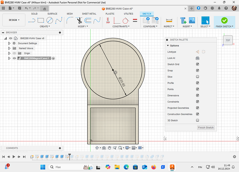
Let’s start designing in Fusion 360 by creating a new component and attaching a sketch to the origin. A suitable wall thickness is typically 2 mm, and the sliding clearance is 0.2 mm, which corresponds to one layer’s height. Begin by drawing the outer outline of the base section. In this sketch, you can see both the space reserved for the sensor, which is the sensor’s PCB dimensions plus 0.2 mm, and the area designated for a 20 mm neodymium magnet. Think of this sketch as the bottom layer relative to the printer’s build plate. Use the offset tool when creating the walls.
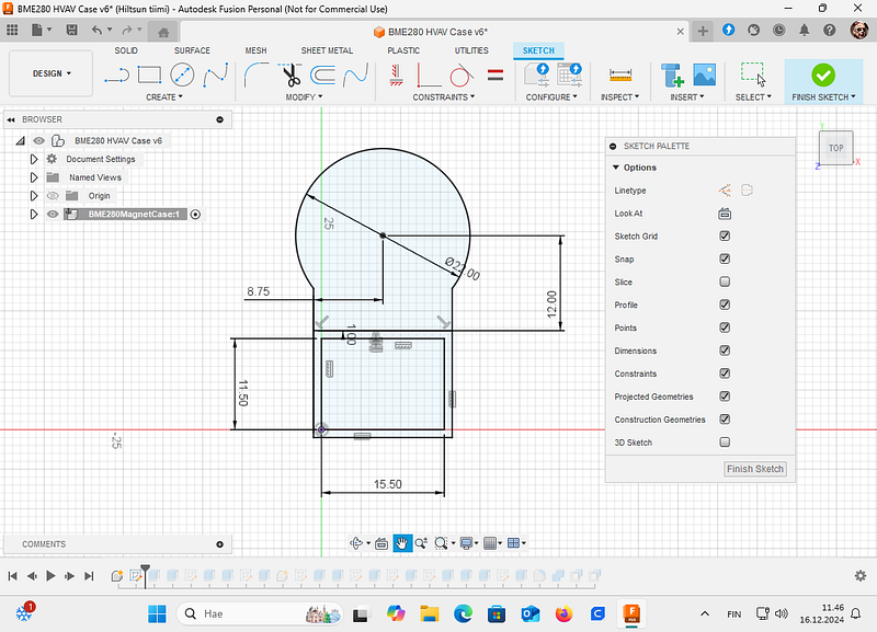
Sketch for the bottom part of the sensor case
🧠 Pro Tip – Link Components to Avoid Mismatches
Instead of redrawing the lid from scratch, use Project (Sketch > Project/Include > Project) to bring the outer edges of the base into the lid’s sketch. This creates a parametric link: if the base width changes, the lid updates automatically. Also, set the lid’s outer rectangle as BaseWidth + 2*WallThickness + Clearance using parameters.
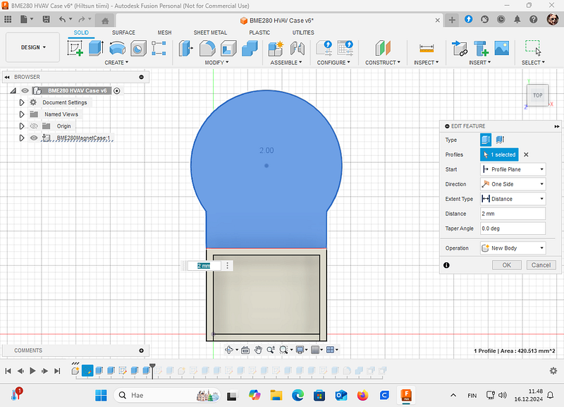
Next, extrude the sketch to create a 2 mm thick base. In this image, it is shown in blue.
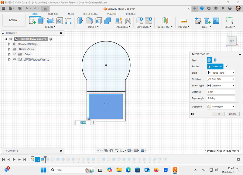
Extruding 2 mm
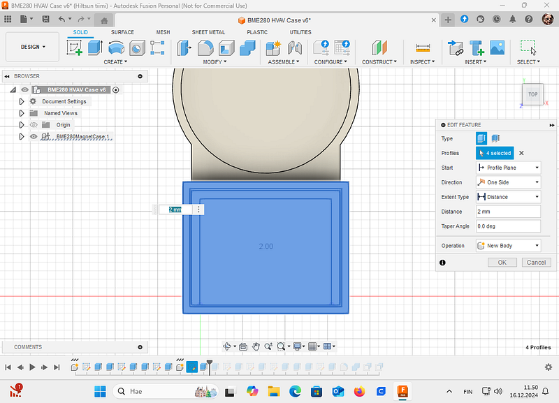
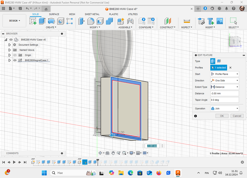
Next, extrude the sketch to create 2 mm thick walls 5 mm upwards. In this step, you can choose “join” differently from the image, or combine the parts together later (if you used New Body like in the image).
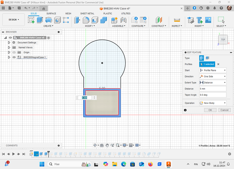
Extruding walls
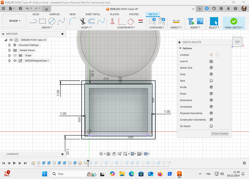
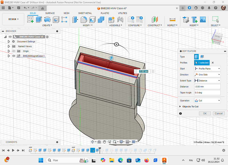
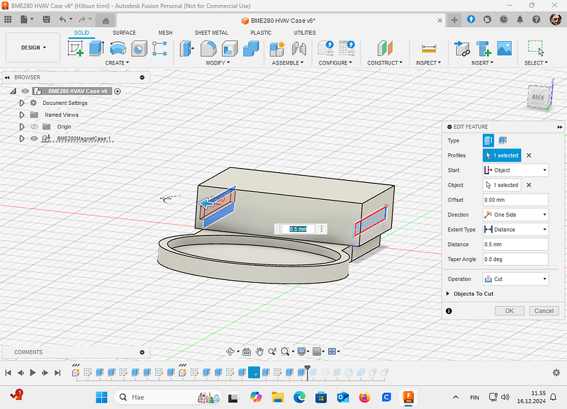
Next, create a slot in the base part for the cables. The idea is that the cables exit the enclosure from the side opposite the neodymium magnet. Anchor the sketch you make for the slot to the corner of the extruded wall.
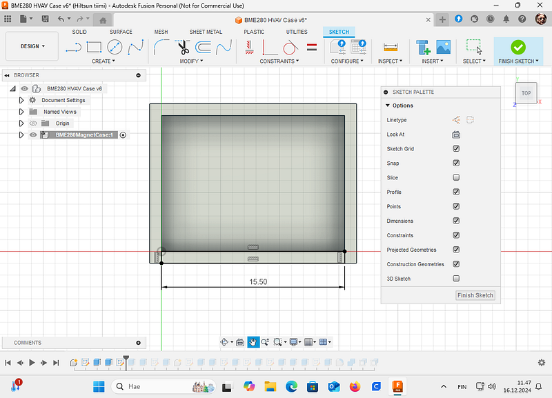
Sketch for the cables exit
Then cut the component 2 mm. With more complex drawings, always open Objects To Cut triangle and check what you are actually cutting!
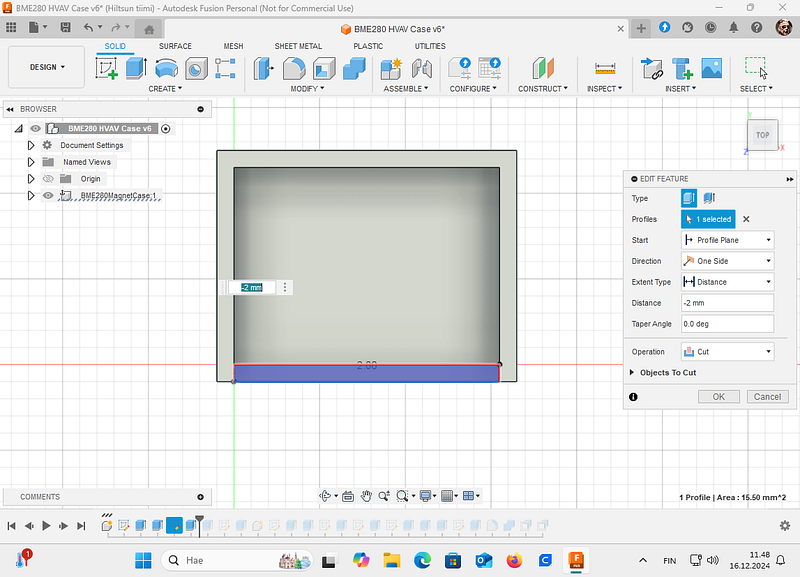
Cutting the cable exit
Next extrude 2 mm the neodymium magnet bottom. This could be done in the first step too, but for demonstration purposes I did this separately:
Extrude magnet base
After extruding the base for the neodymium magnet, create a new sketch with a 20 mm circle. Use the Constraints tool if needed to center the circle on the first sketch.
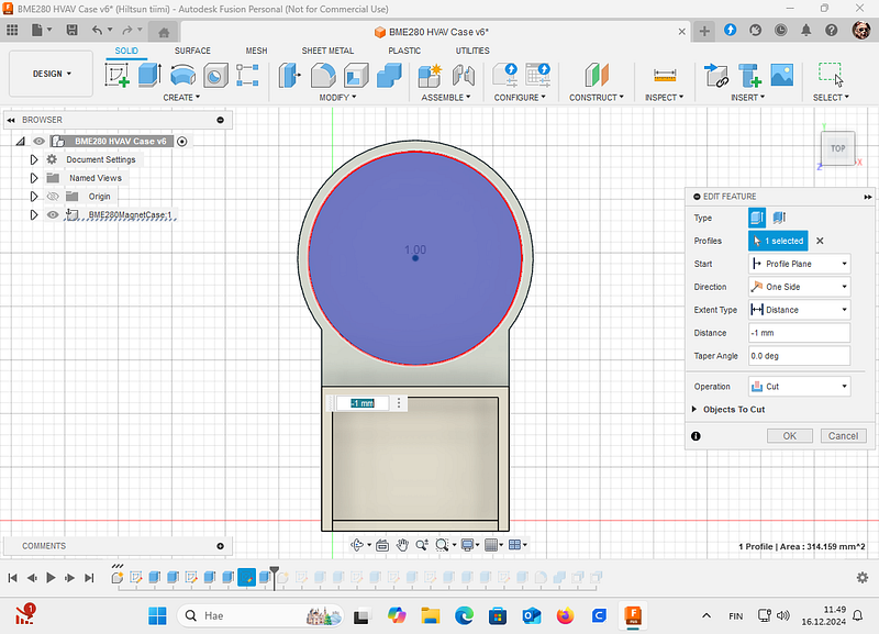
Cut for the magnet
Next cut with above sketch the bottom -1 mm. This means that your neodymium magnet base thickness is 1 mm.
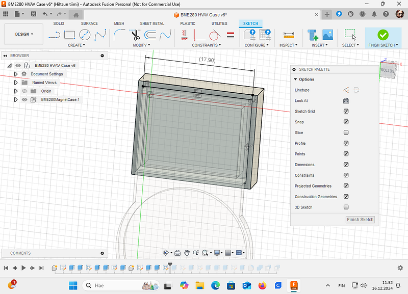
Next, we will create the lid. Select New Component and create a new sketch at the height of the enclosure’s base wall. In other words, click on the wall, select New Sketch. Using the dimensions of the base, draw a lid that is 1 mm wider. We will leave a 0.2 mm gap between the lid and the base, and we will extend the lid’s walls downwards later.
With the sketch, select all squares and extrude 2 mm as a New Body:
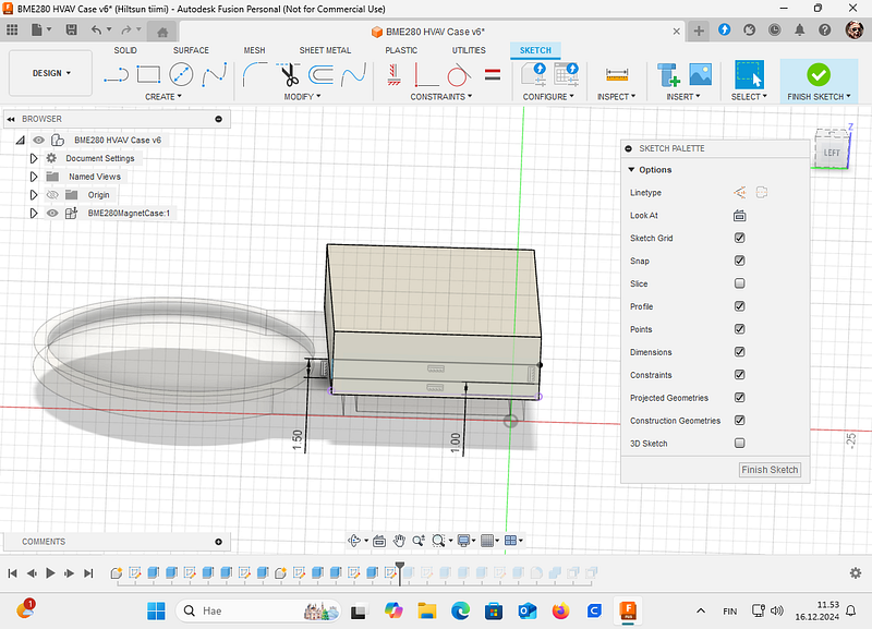
Next, select the outer square from the sketch and use it to create 3 mm deep walls that extend over the base part. Note that you should use the “Join” operation.
Next, create a recess for the cables in the lid by making a sketch on the underside of the lid. Remember to link the dimensions to the reference point you choose, as this makes it easier to adjust the proportions when the dimensions have a reference point.
Then Cut 3 mm from the lid:
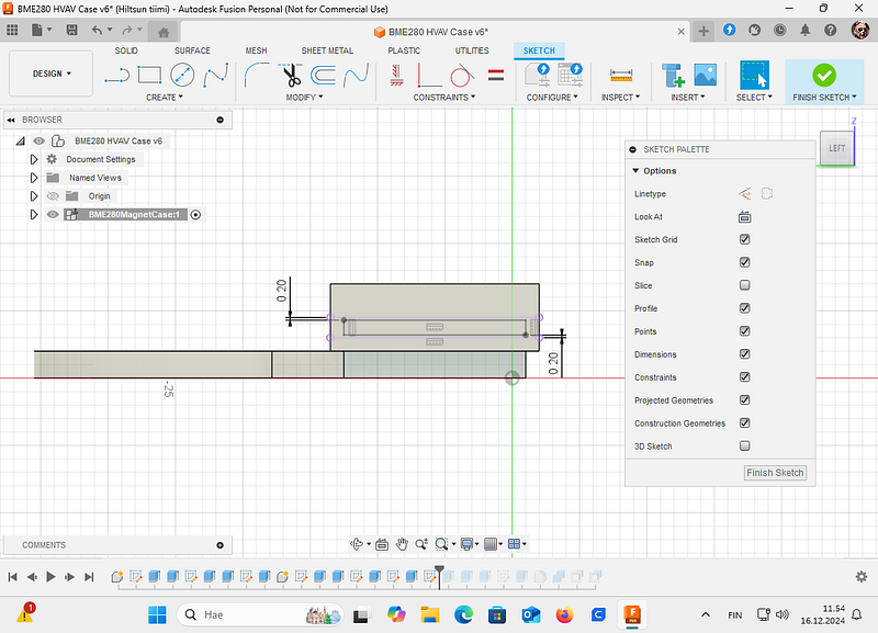
Next, we will create sliding rails for the lid and the base using a single sketch. We will make a small raised section on the base, which will be cut out from the lid. This will leave a 0.2 mm sliding gap in between.
First Cut 0.5 mm from the lid left side:
Then make new sketch and lead 0.2 mm space as a sliding gap:
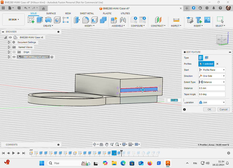
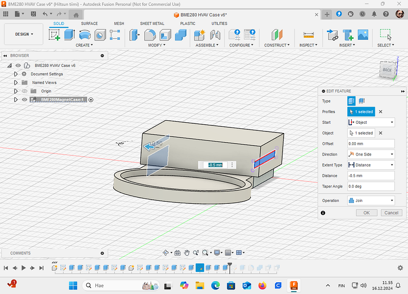
Then with the 0.2 smaller sketch extrude and join 0.5 mm to the bottom part:
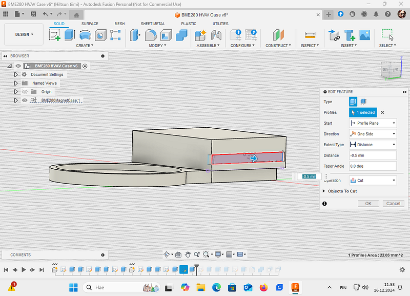
By using the same sketch, use Object (right side) as a start and cut 0.5 mm:
And then with the very same sketch extrude 0.5 mm to the bottom to right side. Remember to select Start as a object:
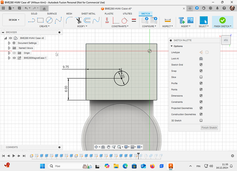
Lastly we will make a hole for the BME280 sensor. Create new sketch to the lid:
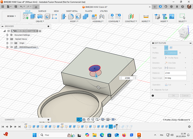
And then cut the hole to the lid:
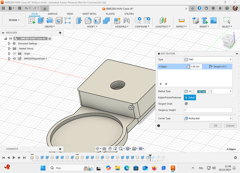
Lastly, for eyes round corners looks better, so, select the lid corners and round them 1 mm. Remember, that rounding too much decrease material thickness too.
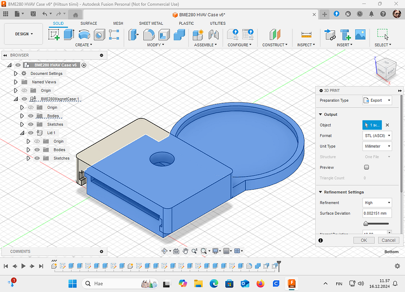
Now you are ready to print the sensor case. In this example I have first combined bottom parts into one and then creating STL file for the 3D sliding program (Ultimaker Cura):
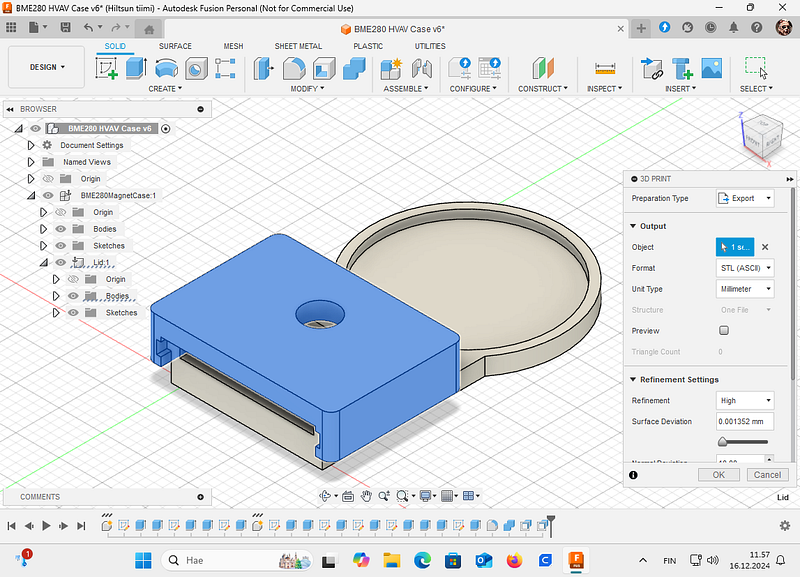
And the lid:
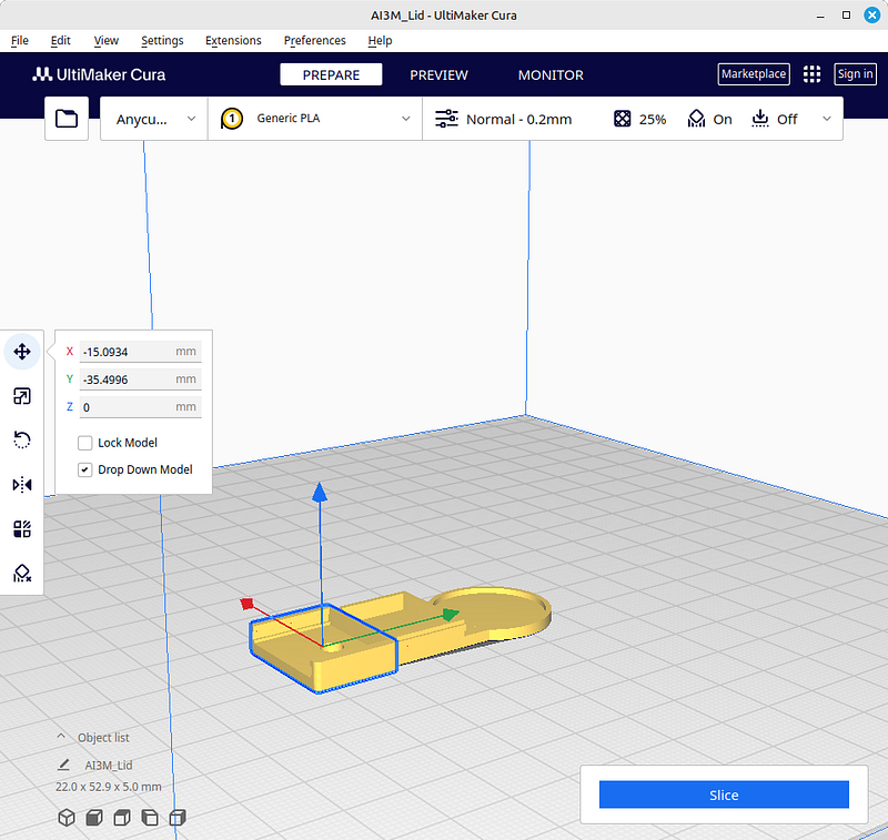
Then we need to slice the STL files for printer. I use Ultimaker Cura. If you use a Linux-version of the Cura, you might notice that File Open and selecting STL files do nothing. This is known bug in the Linux Cura version. Just wait. They will appear there in a minute.
First select which material you are going to use, PLA, PETG etc. and then proper parameters for the filament. Cura in fact has very good defaults. Then move objects on the build plate as you think fits for your printer and select the lid’s top facing to the build plate:
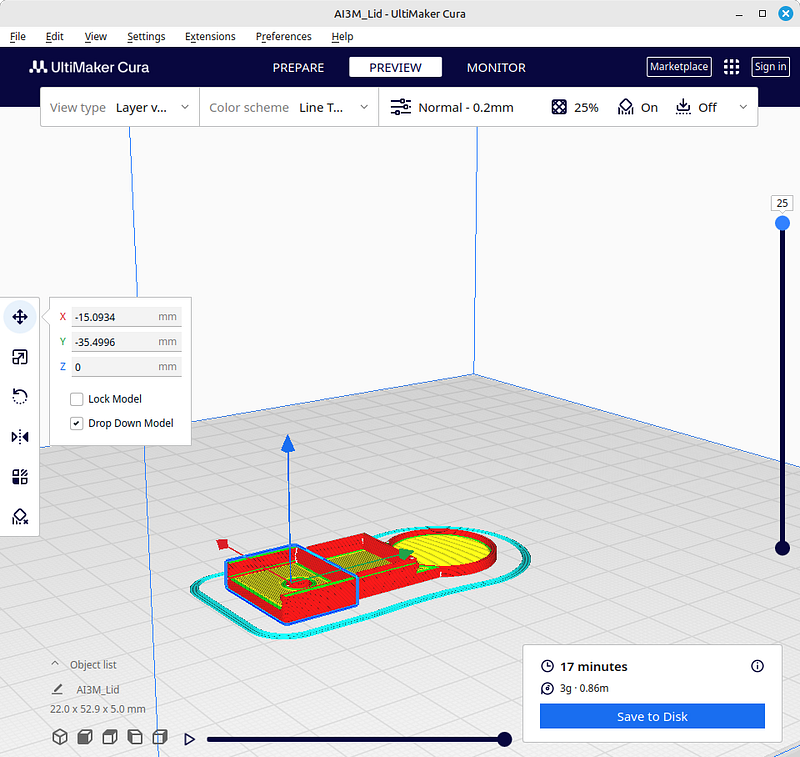
Then just slice the work and print objects out:
After printing and cooling, remove supports and check if your design works.
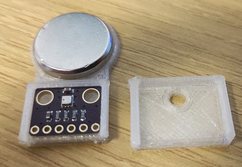
3D printed sensor case for BME280 to be installed with a magnet to the HVAC system
✅ Pro Tip – Test the Sliding Fit Before Printing Everything
Print only a 5 mm high cross‑section of the lid and base to verify the 0.2 mm clearance. Adjust the Clearance parameter if the fit is too tight or too loose – then the full print will be right the first time.
🔗 Pro Tip – Keep Your Fusion 360 Assembly Organised
Use Components (not separate bodies) for the lid and base. Then use Joints (Assemble > Joint) to simulate how the lid slides onto the base. Even if you don’t animate, this helps catch interference before exporting STLs.
As you can see, turning an idea into reality isn’t ultimately very difficult if you understand the process. Hopefully, this simple example will help you move forward with your own projects. It’s also worth remembering that you don’t have to do everything yourself, many platforms share free 3D objects ready for printing.
My 3D Design objects are here. If you need my micropython code for these cadgets, look at my code at Codeberg here.
Good luck and success with your projects!